To design a good shut-off system we will need to know what forces are acting on a flying combat model.
There is a lot of guess and rumours on line tension and g-forces but it would be nice to know what the real values are for a flying model.
A critical parameter for a shut-off system based on line tension is at what line tension the engine shall be stopped.
To set this "shut-off line tension" we must know what the line tensions are under normal conditions and what line tension we can expect in a fly-away.
In this "Fact Finding Mission" we first will try to calculate the forces on a combat model under normal flying conditions.
Then we will try to measure on a flying model just to make sure that we got things right.
Finally we will try to set up an experiment to give us an idea of the line tension in a fly-away.
At the end it is our hope to be able to set a value for the "shut off line tension" that is based on facts from this mission.
Calculating the line tension
It is possible to calculate the theoretical line tension from model weight, flying speed, line length and flying height.
Here is a plot that will give you an idea of the theoretical line tension on a normal combat model.
The calculated line tension is plotted against the flying speed for a 450 g model flying horizontally at 15.92 m line.
To make these calculations easy for everyone to do I have set up a
"Control Line Calculator".
Here you can not only make calculations on line tension but also on g-force in loopings, g-force in crash landings and more.
Play around with the calculator and you will get an idea about the line tensions and forces in different flying situations.
Measuring the line tension
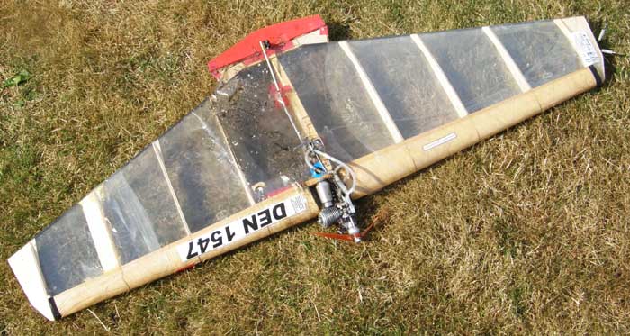
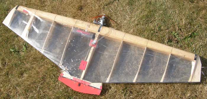
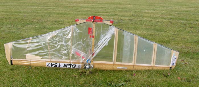
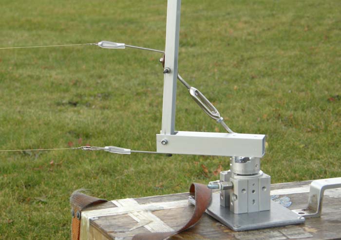
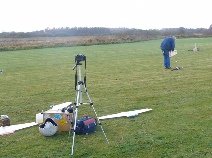
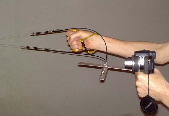
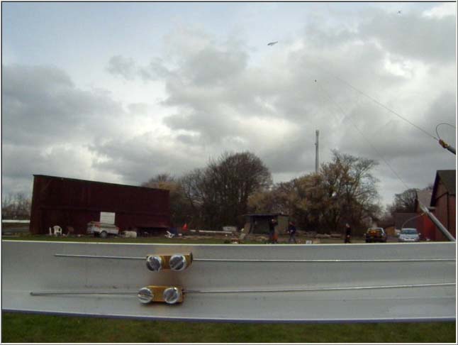
I built this system to measure the line tension on a flying model.
A couple of springs have been inserted between the handle and the lines.
The deformations of the springs are transferred to a ruler via two Bowden cables.
The ruler is fixed to a camera and it is possible to shoot a video that will show both the line tension and the maneuvers at the same time.
There is some slack in the cable system but you get a pretty good idear about the line tension during a normal flight.
There is no scale on the force-meter but you can compare the positions in the demonstration to the positions during the flight
(No!!! - don't use a permanent marker on your screen!).
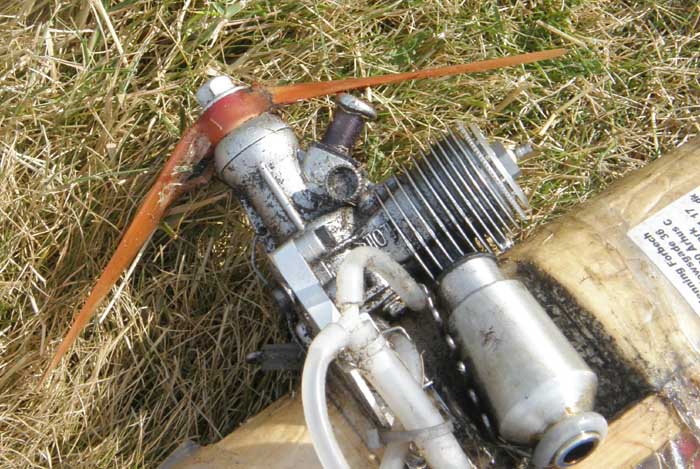
See the video clip (29 Mb avi-file) from a test flight with a Fora engine on a ViKo model.
The line tension is between 40 N and 45 N in normal flight but goes down to about 30 N in the loopings.
In this flight the line tension never seems to be less than 20 N.
g-force in loopings
There have been a lot of wild guesses on how small a loop a combat model could make and how high the g-force would be in this loop.
A video camera and some calculation is all it takes to measure the size and to find the g-forces in a loop!
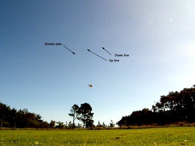
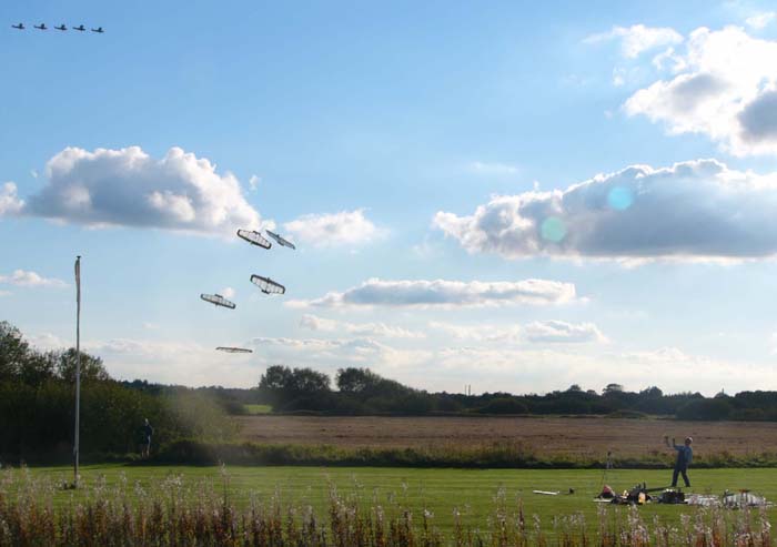
This image was made form a short video sequence of a flying model.
The video was shot with 30 frames pr. second and with the handle right at the camera.
The camera was on a tripod at the ground and kept steady in a fixed direction.
The model was flown through the loop at maximum ruder deflection. To get the smallest possible loop the down line was pulled by hand.
On this enhanced image you can actually see how the model is hanging on the down line.
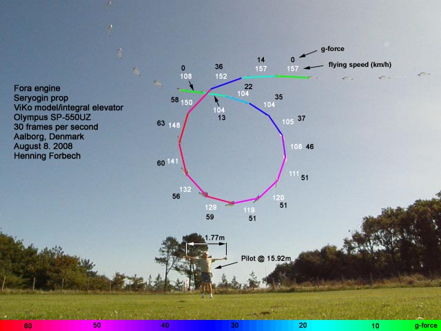
By measuring the distance between the models in the images it is possible to find the actual flying speed through the loop.
Also the turning radius can be found and the g-force can be calculated for each position in the loop.
The flying speed is here shown in white text and the g-force in black text for each section of the loop. The diameter of the loop is about 4.5 m
Fotos from another loop that day.
And a loop close to the ground.
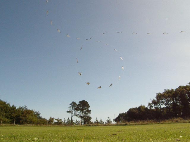
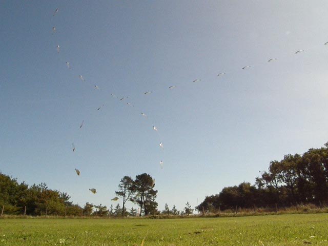
In this photo from last winter a model is doing a long series of very small loops.
The diameter of the loop is 3.7 m. The flying speed is 20.3 m/s (73 km/h) and the load is 23 g.
I was surprised that the flying speed could be that low in tight maneuvers.
The model is here flying without a streamer but with a streamer the flying speed could be even lower.
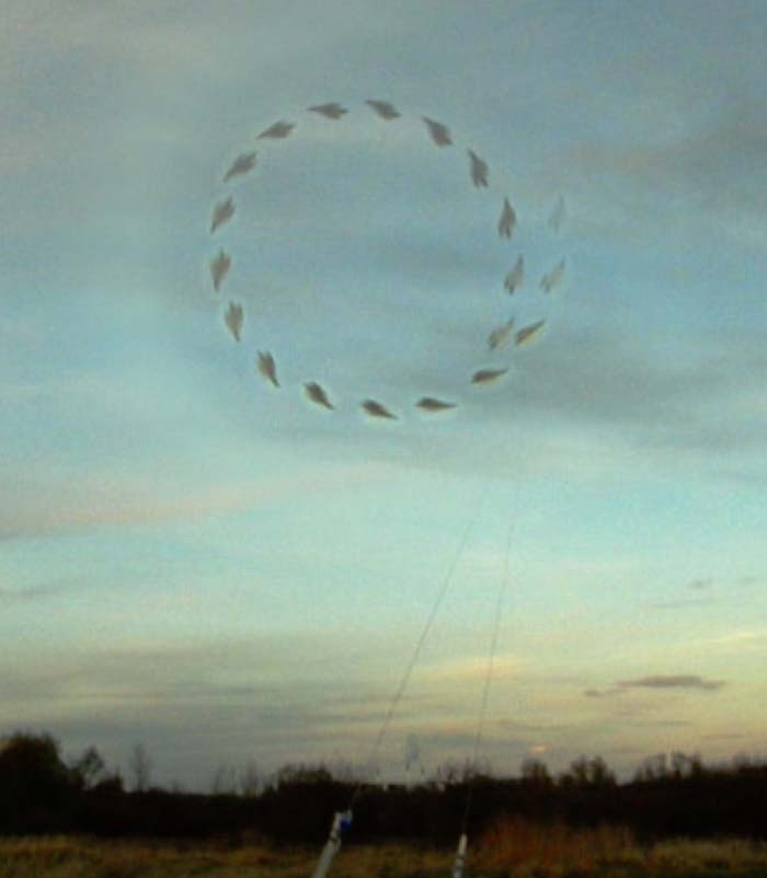
The loop in this photo sequence is the last complete loop at the end of this video clip (25 Mb avi file).
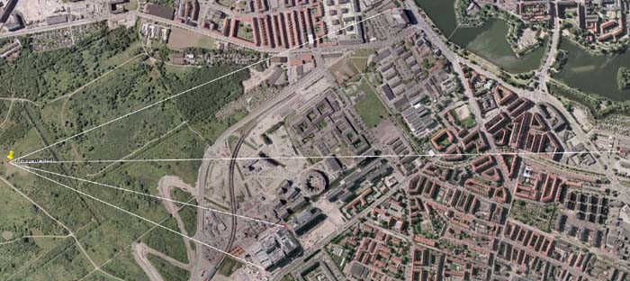
In this experiment the size of the loop was found by comparing the position of the model to the buildings in the back ground.
The angle between the buildings was found on a map of the flying field.
The diameter of the loop could then be calculated from the angular size of the loop and the line length.
Just a nice photo from an earlier attempt to measure the size of a loop.
Line tension at a fly-away
The goal of the next experiment is to find a realistic "shut off line tension".
It will be very difficult to measure the actual line tension in a real fly-away so we will try to get some data
from a similar situation.
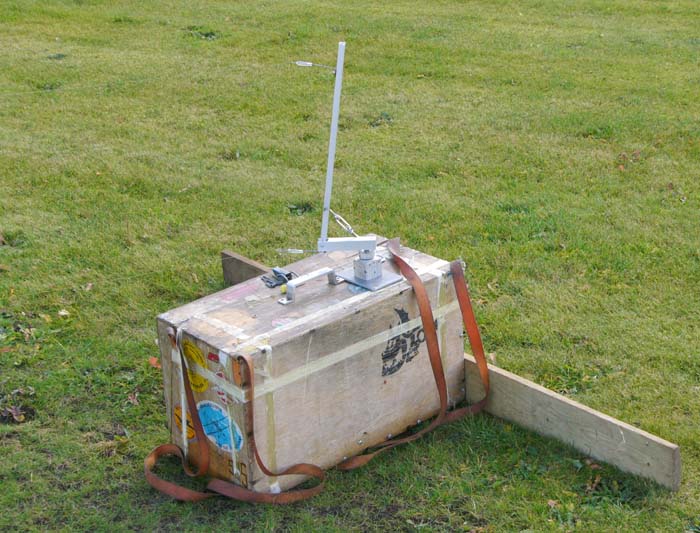
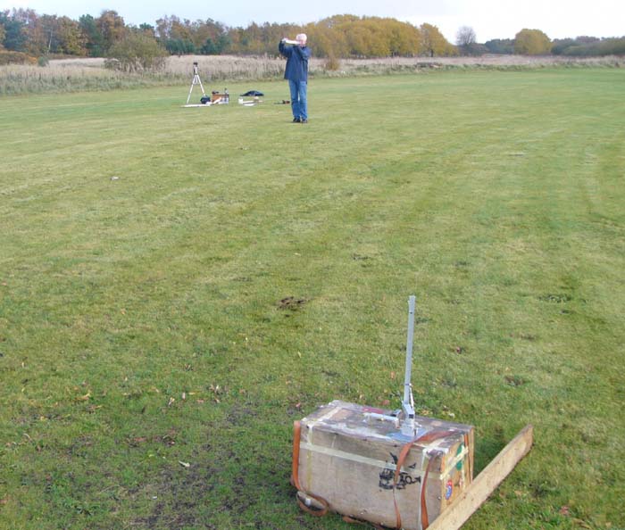
The idea is simply to measure how much force it will take to pull a set of lines after a flying model.
This is not the same as a real flyaway but the conditions are pretty close to a flyaway so we should get a good indication of what the line tension would be in a flyaway.
Instead of directly measuring the force it takes to pull a set of lines we will estimate the value by comparing it to the force it takes to pull normal a streamer.
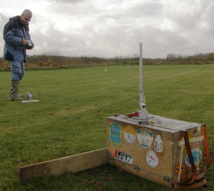
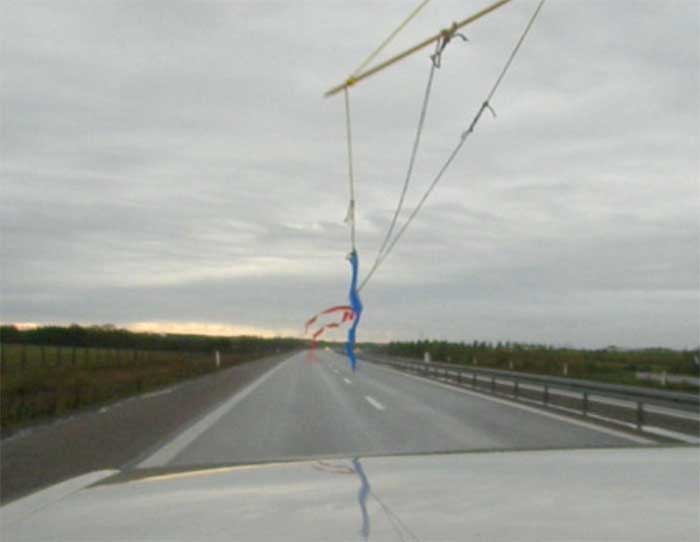
So, first we have to find out how much it takes to pull a streamer after a model. With a spring scale, an old car, an empty highway and couple of combat pilots we are ready to measure some different streamers.
See a video clip (15 Mb avi-file) from the highway experiment.
The result from the highway test was:
Plastic streamer (from Nikolai Necheukin): 1.8 N @ 36 m/s
Paper streamer (from Mejzlik): 3.2 N @ 36 m/s
Special test streamer from heavy tissue: 3.5 N @ 36 m/s (36 m/s is equal to 130 km/h)
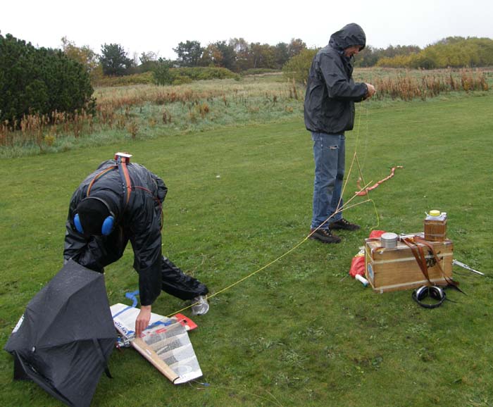
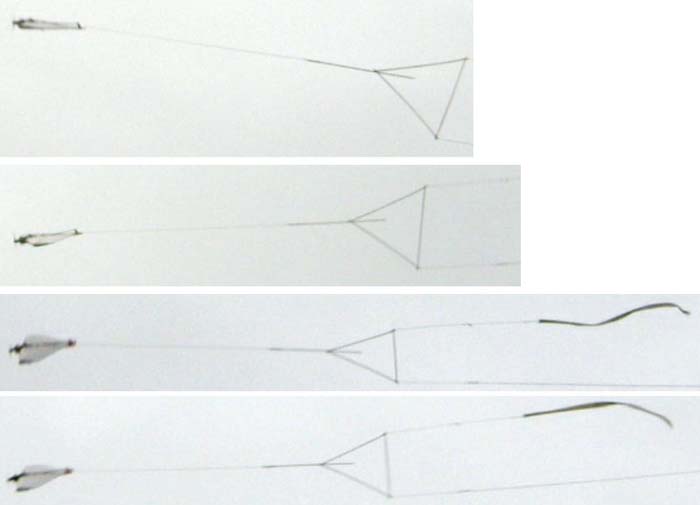
With these streamer data we are ready to make some experiments with a flying model.
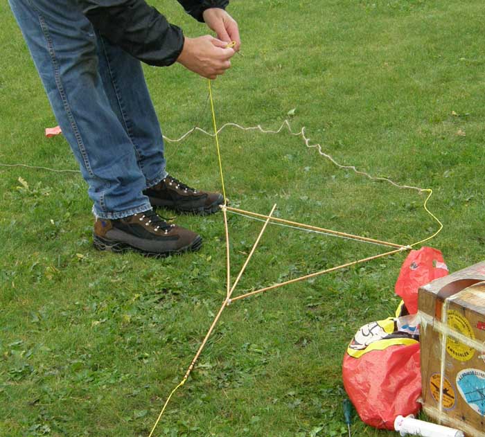
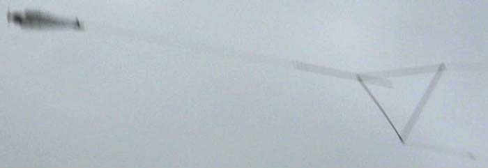
With a simple triangel made from 5 mm wood sticks we can pull two streamers after a model.
With a streamer in each corner and the string to the model in the third corner we have a kind of lever-balance.
By observing the behavior of the triangle we should be able to determinate the relation between the forces on the two streamers.
Cold and rainy weather for the test. See the video clip (4 Mb avi-file).
In the first flight we just test the measuring system by comparing two of the known streamers.
Here is some pictures from the heavy streamer versus the plastic streamer.
From the images of the test flight it seems that the force it takes to pull the plastic streamer is 70% of the force it takes to pull the heavy tissue streamer.
In the highway test we messured the heavy tissue streamer to 3.5 N @ 36 m/s so the plastic streamer should be 2.45 N @ 36 m/s.
We messured it to 1.8 N so there is a mishmatch of (36% - 27%) ~30 %.
This differens is OK as long as we just want to get an idear of the forces involved.
Next we made a test flight with a set of lines (no handle) versus the heavy streamer.
As you can see the force its take to pull a set of lines are less than the force it takes to pull a plastic streamer.
From the images the force can be found to be equal to 1.5 N. This is at a speed of 32 m/s (130 km/h). A more realistic flyaway speed is probably 42 m/s (150 km/h).
Since the drag rise with the squeare to the speed we must expect the tension from a set of line whitout a handle will be aproxamatly 2 N.
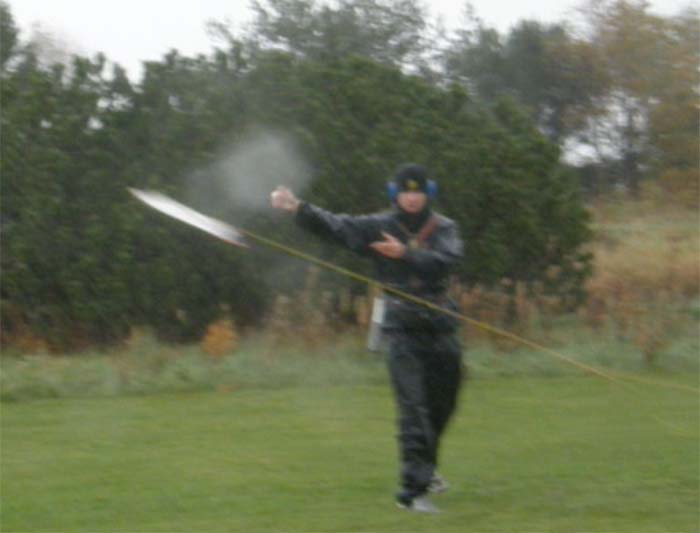
At the last test we flew a full set of lines with a handle against the heawy streamer.
This experiment was a little tricky. The handle at the end of de lines would swing out of the circle as soon as the model gaine some speed.
We did not know how far it would swing out so the mechanic had to run for cover as soon as he let the model loose.
We got the model in the air with out any problems. The weight of the handle was 72 grams and it swing aproximatly 8 m out out of the flying circle.
The force from the line and handle in this test was around 6 N
Standard Work Space
Now we have enough information to set up a general picture for the g-force on a flying combat model.
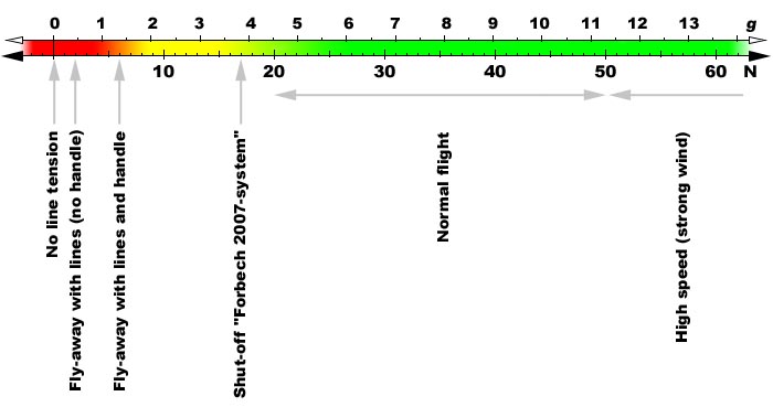
First we will show how the values for line tension are distributed.
The Line Tension is calculated for a typical 450 g horizontal flying model.
The Centripital Acceleration is shown on the same axis (as g-force).
The line tension shown is only based on the Centripital Force.
Additional line tension from the model "hanging" on the lines (typical effect from extra tip weight) is not taken into considerations.
The force from the gravity is also not incorporated. Worst case cenario where the model is situated at the top of a wing over the g-force will be reduced by 1 g.
Engine offset, gyro effects and other "exotic" forces are not included.
The reed zone are situations where the model is in big trouble, probably in a fly-away.
The green zone are the normal values for a flying model.
The yellow zone are the critical situations where the line tension is to low to be a normal situation.
The shut-off system should allow the engine to run as long as the model is in or close to the normal zone.
If the model moves into the yellow zone the shut-off must stop the engine before it enters the red zone.
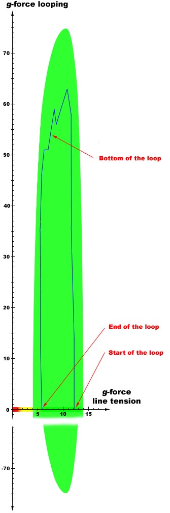
The theoretical g-forces in loopings can be calculated from the size of the loop and the flying speed.
You can do these calculations with the "Control Line Calculator"
These forces are perpendicular to the Line Tension so we must use a coordinate system to illustrate it.
With the same scale on both axis we will see the figure shown to the right.
The g-force from loopings can be positive and negative (inside and outside loops).
To reduce the size of the illustration the negative axis is cut short .
The green area shows the normal work space for a combat model.
The maximum g-force in looping is set to 75 g.
This is an assumed value and could differ greatly.
The shape of the green area is assumed too.
It might come as a surprise for you how large the g-forces from loopings are compared to the g-forces from flying on lines in a hemisphere.
A shut-off system must be designed to work under these conditions.
Remember these high g-forces are not just some peak values that only seldom occur.
The large g-forces and the fast change from positive to negative g-forces are the conditions for a combat model.
Any shut-off system must be resist with this load and remain operational for a long period.
In midair collisions and crash landings the g-forces can be extremly large for short periods.
The shut-off system must be able to resist these forces and must remain operational after theese types of incidents.
We also have data of the g-force in loopings.
These values are shown at the same figure.
The blue line in the green area is the values from the loop in the video sequence above.
The CTM combat pilots in Munich, Germany also got some studies
of the g-force on a flying model. Results can be seen here.
Shut-off line tension
I think the line tension we saw for a fly-away with lines and handle is a realistic value.
The handel on a fly-away model might jerk around a lot.
These jerks will probably be suficiant to activate the shut-off, however it will only be over a very short period of
time and will not affect the fuel supply to the engine.
I have carried out aproximately 5 "let-go-of-the-handle"
tests with my 2007 system. All tests were carried out with a relatively heavy handle and the shut-off line tension was set to 17 N.
The results of the tests and the calculations found on this page have given me confidence to decrease the shut-off line tension on the 2009 system to 10-12 N
(equals 2.5 g in the line direction).
Some will might state it would be sufficient to design the shut-off system for a situation where the model is flying away with cut lines.
This situation will requie a realtive low shut-off line tension and minimize problems with control during
takeoff, landings or flying up wind.
The shut-off system must not only be designed for the "classic" fly-away situations where the lines are cut.
The situation where the model will fly-away with the complete set of lines and handle because your pitman
let the model off before you get a proper hold on the handle must also be taken into consideration.
The shut-off system must be able to stop the engine in this situation to avoid surroundings and paticipants are exposed to danger.
If you deliberately designe or adjuste your shut-off not to act on this situation you can face an action for damages.
This also apply competition organizers and judges that allow pilots to fly with shut-off systems with a very low shut-off line tension.
To make sure that a decent number of pilots still participate in competitions is it nessesary to accept more relaxed systems in the first season under the
new rules. Simple swing-arm systems and string-over-the-wing systems can be good start solutions for many pilots and overall combat will be far more safer
than previously.
I hope the information on this web page will support the development of better and more reliably shut-off systems.
31/1 2009
/Henning Forbech
Crash Test
Hard landing with F2D model. Fora engine and ViKo model.